Getting started
Project directory organization
To be executed, a PyStack3D workflow requires both:
a
params.tomlfile defining all the process steps parameters (see the parameters settings section)a project directory including the
.tifimages named with their respective slice numbers and their z-positions either in the root directory:
project_dir
    |-- params.toml
    |-- slice_0000_z=0.0000um.tif
    |-- slice_0001_z=0.0100um.tif
    |   ...
or in sub-folders for a multi-channels acquisition:
project_dir
    |-- params.toml
    |-- channel_1
    |       |-- slice_0000_z=0.0000um.tif
    |       |-- slice_0001_z=0.0100um.tif
    |           ...
    |-- channel_2
    |       |-- slice_0000_z=0.0000um.tif
    |       |-- slice_0001_z=0.0100um.tif
    |           ...
Once executed, the outputs directories related to each process step can be found inside the process directory as follows:
project_dir
    |-- params.toml
    |-- slice_0000_z=0.0000um.tif
    |-- slice_0001_z=0.0100um.tif
    |   ...
    |-- process
    |       |-- cropping
    |       |       |-- outputs
    |       |       |-- slice_0000_z=0.0000um.tif
    |       |       |-- slice_0001_z=0.0100um.tif
    |       |           ...
    |       |-- bkg_removal
    |       |       |-- outputs
    |       |       |-- slice_0000_z=0.0000um.tif
    |       |       |-- slice_0001_z=0.0100um.tif
    |       |           ...
    |        ...
or for a multi-channels acquisition:
project_dir
    |-- params.toml
    |-- channel_1
    |       |-- slice_0000_z=0.0000um.tif
    |       |-- slice_0001_z=0.0100um.tif
    |           ...
    |-- channel_2
    |       |-- slice_0000_z=0.0000um.tif
    |       |-- slice_0001_z=0.0100um.tif
    |           ...
    |-- process
    |       |-- cropping
    |       |       |-- outputs
    |       |       |-- channel_1
    |       |       |       |-- slice_0000_z=0.0000um.tif
    |       |       |       |-- slice_0001_z=0.0100um.tif
    |       |       |       |   ...
    |       |       |-- channel_2
    |       |       |       |-- slice_0000_z=0.0000um.tif
    |       |       |       |-- slice_0001_z=0.0100um.tif
    |       |       |       |   ...
    |       |-- bkg_removal
    |       |       |-- outputs
    |       |       |-- channel_1
    |       |       |       |-- slice_0000_z=0.0000um.tif
    |       |       |       |-- slice_0001_z=0.0100um.tif
    |       |       |       |   ...
    |       |       |-- channel_2
    |       |       |       |-- slice_0000_z=0.0000um.tif
    |       |       |       |-- slice_0001_z=0.0100um.tif
    |       |       |       |   ...
    |        ...
(The content of each ‘outputs’ directory is detailed below)
Warning
As illustrated above, following each process, images of the entire processed stack are saved. Consequently, this requires having a sufficient amount of free disk space.
For instance, in the case of a stack of 2000 images sized 2000x2000 encoded in 16 bits, each process step will require storing approximately 15GB of data.
To facilitate the cleaning of these large volumes of data, a cleanup() function was created (see the Workflow execution section below).
Workflow initialization
All the workflow instructions are provided in a params.toml.
A raw params.toml is given here (to be adapted according to needs).
Case of a Zeiss FIB-SEM
In the case of Zeiss FIB-SEM acquisitions, some metadata produced by the software for 3D acquisition (Atlas, developped by Fibics) can be automatically extracted from the .tif image files and the Atlas3D.a3d-setup file. Based on these, the default parameters for the processing can be adapted as follows:
from pystack3d.utils_metadata_fibics import params_from_metadata

params_from_metadata(project_dir, save=True)
where project_dir refers to the project directory pathname containing the Atlas3D.a3d-setup file (mandatory file), and the .tif files in sub-directories corresponding to different channels (at least one slice in the first channel directory is required).
This will save a params_from_metadata.toml file based on the raw one but adapting some of the parameters to the acquisiton with the help of the extracted metadata.
The affected parameters are listed here:
Name of the channels is read in the
Atlas3D.a3d-setupfile.For the cropping step, area is defined based on the ROI of the first slice and will not take into account changes of ROI that might have been made during the acquisition.
For the resampling step, dz is read in the
Atlas3D.a3d-setupfile
On top of that, the function checks that the first slice is square and that the field of view of the Atlas3D.a3d-setup file corresponds to the first slice size.
By default, the reference params.toml file used by params_from_metadata for all the other parameters is the raw one. But the user can provide another reference .toml file through the fname_toml_ref argument:
params_from_metadata(project_dir, save=True, fname_toml_ref=my_toml_ref)
Workflow execution
A PyStack3D workflow execution is obtained with the following instructions:
from pystack3d import Stack3d

stack = Stack3d(input_name)
stack.eval(process_steps, nproc=16)
input_name corresponds either to the project directory pathname or to the params.toml in which the project directory pathname has to be defined via the input_dirname parameter.
process_steps refers either to a single process step or to a list of process steps or can be omitted leading to the execution of the full process steps defined in the ``params.toml`:
# execute only the 'cropping' process step
stack.eval(process_steps="cropping", nproc=16)

# execute the 'cropping' and the 'background removal' process steps
stack.eval(process_steps=["cropping", "bkg_removal"], nproc=16)

# execute all the process steps defined in the 'params.toml' file
stack.eval(nproc=16)
nproc corresponds to the number of threads to use for the workflow execution.
Note that an additional boolean keyword named serial allows to realize non-serialized calculations when setting to False (said differently, with serial = False the workflow is executed using the original raw input data for each process step).
At the end of a workflow execution, a cleaning up of all the .tif files (except the ones related to the last process_steps) can be done easily as follows:
stack.cleanup()
At least, to ease the full 3D-stack visualization, .tif files can be concatenated in a single one. See concatenate_tif for more details:
stack.concatenate_tif() # tif files concatenation related to the last process_step
stack.concatenate_tif('input') # tif files concatenation related to the input data
Outputs
Each process steps returns specific and standard outputs (data and figures) in the related process step outputs directory.
Specific outputs are related to each process steps. They are described in each of the process steps sections hereafter (if existing).
Standard outputs consist in the statistics (min, max, mean) on gray values evolution along the stack axis (z-axis, by convention) before and after the process step execution. For the ‘after’ values, the statistics without and with data reformatting compatible with the input data format are plotted. Indeed, some process steps may modify the data type (typically from integer to float) and/or generate data outside the range of authorized data values. (This could happen for instance in the bkg_removal process step when subtracting the background that could generate negative or positive overflowed values).
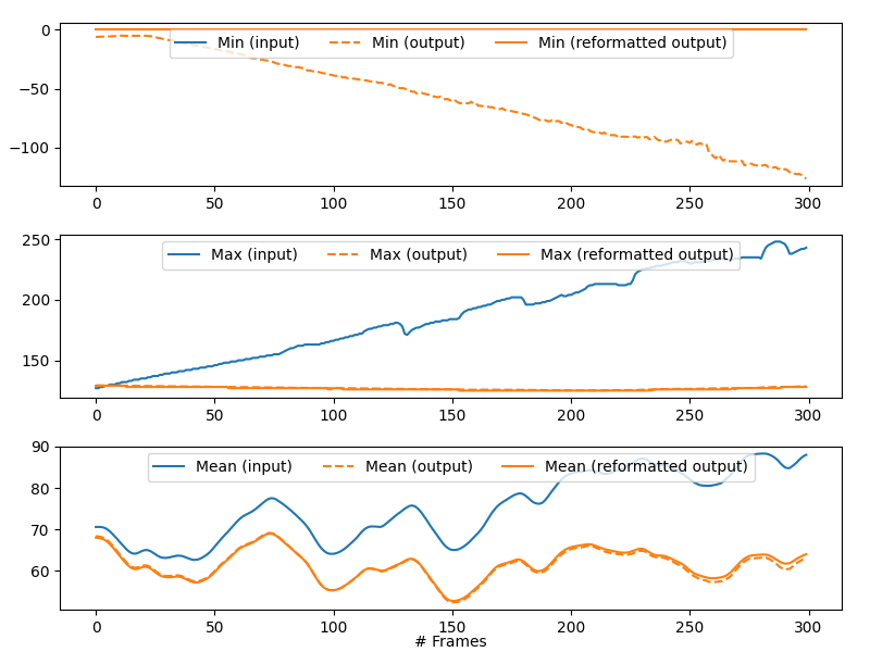
Example of statistics returned by the bkg_removal process step in the synthetic test case.
Examples
Two examples are provided with the pystack3d package github repository.
The first one corresponds to a synthetic stack composed of small images. It aims at providing quick overviews of the process steps outcomes:
cd pystack3d
python examples/ex_synthetic_stack.py
The second one is based on a real but reduced stack (8 slices) issued from a FIB-SEM images acquisition. Although reduced, its execution is longer than the previous one:
python examples/ex_real_stack.py